
 Custom system integration
 Embedded Redesign
 Board Support Package for System Houses
Typical driver scenarios from real-life situations
We encounter these situations particularly often in embedded driver development projects—and we resolve them in a structured manner all the way through to stable production integration.


New module required
Do you have a specific panel, camera module, wireless module, or sensor and need full driver/stack integration? We’ll get the component up and running on your platform—including configuration, pipeline integration, and validation.
Kernel Update / Platform Change
Do drivers work on the old kernel but not on LTS or newer hardware? We’ll port them, resolve dependencies, and bring the integration up to a maintainable standard—without unnecessarily rewriting the product.

Secure your architecture early on
Are you facing selection and architectural decisions (interfaces, bandwidth, DMA, buffering strategy, power management)? We assess the risks early on and define a technically sound integration path.
What you actually receive in the end
Our embedded driver development not only delivers executable code, but also the results of device driver development and system integration necessary for maintainability and mass production:
- Source code and patches in the kernel-level environment
- Configurations for the device tree, kernel, and user-space integration
- A robust diagnostic foundation with logging, tracing, and testing capabilities
- Technical documentation on commissioning, parameterization, known limitations, and operation
- A handover that enables your team to continue working independently
Our Driver Expertise in Practice
The following overview highlights key areas of our embedded driver development—from traditional device driver development and interface integration to stabilization in production devices. This allows you to quickly identify where we can best contribute to your system—from displays and cameras to communication and I/O.
Application in the Product
Stable display output in the production unit—including correct timing, backlight/power sequencing, boot and standby behavior, and seamless integration into the OS graphics pipeline.
Common real-world issues
- Flickering, artifacts, sporadic black screens (timing/power/link training)
- Resume/suspend unstable, backlight hangs, incorrect initialization order
- Graphics pipeline/overlay handling causes stuttering or non-reproducible states
Our Output
Reproducible display state: panel connection (timing/power/backlight), stable pipeline configuration (e.g., DRM/KMS), documented operating modes, and robust behavior across boot/resume/continuous operation.
Brief explanation
MIPI DSI: Serial display interface; lane-/clock-driven, highly timing- and board-dependent
LVDS: Differential interface; robust, often via bridge/panel-specific timings
RGB: Parallel pixel bus; very timing-critical, layout/EMC have a stronger impact
Product Application
Reliable camera and sensor connectivity with a defined frame rate/latency and reproducible image quality—from the module to a stable stream in the target system.
Common Real-World Issues
- “No image”/sporadic frame drops (bandwidth, buffering, DMA)
- Start/Stop, Reconnect, or Resume interrupt the stream (Recovery missing)
- Format/bit depth/clocking mismatch (pipeline does not match the sensor/SoC)
Our Output
Stable camera integration status: sensor/module connection, reliable streaming modes, robust error handling (timeout/reinit/recover), and a pipeline that runs reproducibly in the production device.
Brief explanation
- MIPI CSI-2: Serial camera interface; high data rates, sensitive to lane/timing/SoC pipeline
- Parallel (DVP): Pixel bus with PCLK/HSYNC/VSYNC; timing- and layout-dependent, often used in legacy designs
Product Application
Reliable audio path integration (capture/playback), including codec connectivity, synchronous clocking, and stable power states—without dropouts and with controllable latency.
Common Practical Issues
- Crackling/dropouts (clocking, DMA, buffer underruns)
- “No sound after resume” (routing/power state/initialization order)
- Drift or incorrect sample rates (master/slave clocking, PLL setup)
Our Output
Stable audio performance: clean clocking/routing, codec connectivity, defined audio paths, reproducible sample rates, and robust behavior during start/stop/standby/load.
Brief explanation
- I2S: Audio data bus SoC↔Codec; master/slave clocking is critical
- PCM: Frame/slot-based digital audio transport; commonly used for telephony/multichannel
- PDM: Bitstream (typically digital microphones); requires decimation/filtering
Use in the Product
Reliable input in the device – consistent event transmission, correct mapping/rotation, multi-touch (if applicable), and reproducible behavior across all operating states.
Common Issues in Practice
- Touch is occasionally not recognized / Reconnection is unstable
- Ghost touches or inconsistent multi-touch (noise/filter/protocol)
- Problems after sleep/resume (init/IRQ/power states)
Our output
Maintainable input standard: clean driver integration, stable device detection, correct event mapping, and robust handling of edge cases (reconnect/resume/timeout).
Brief explanation
- USB: Often HID-based; enumeration/reconnect and power supply are typical levers
- I2C: Most common touch controller bus; bus quality/IRQ path are critical
- SPI: Higher data rates/determinism possible; keep chip select/timing clean
Application in the Product
Deterministic control of actuators – stable timings, reliable default states, defined ramps/control paths, and reproducible behavior during restarts or in the event of errors.
Typical Real-World Problems
- Jitter/timing fluctuations (timer setup, priorities, load)
- Incorrect default states at boot or after a brownout
- Missing recovery/fail-safe logic (restart, emergency stop, monitoring)
Our output
Deterministic control state: robust PWM/timer paths, defined initialization/fail-safe states, reproducible control, and diagnostic capability for field errors.
Brief explanation
- PWM: Control variable for power/speed/dimming; note jitter and power states
- Stepper motor: Usually via driver IC (Step/Dir or SPI/I2C); timing/ramps are central
- Laser: Module/IC-dependent; focus on stable control and defined operating states
Use in the Product
Cross-functional modules for configuration, sensor technology, analog measurement/output, and basic I/O—the foundation for stable peripherals in many devices.
Typical Real-World Problems
- Bus timeouts/NACKs, sporadic dropouts under load
- Incorrect initialization order / IRQ handling
- Measurement drift/noise (references, sampling, triggers, layout influences)
Our solution
Robust I/O architecture: clean bus access with error handling, defined initialization, traceable ADC/DAC paths (sampling/calibration where relevant), and stable GPIO/interrupt connectivity.
Brief explanation
- I2C: Multi-device bus; robust error handling is mandatory
- SPI: Faster and deterministic; chip select/timing is critical
- ADC/DAC: Analog↔Digital; sampling/references/triggers determine quality
- IO/GPIO: States/interrupts/wakeup; default states and debouncing are important
Product Application
Stable peripheral and data connectivity, including hot-plugging and field operation—from touchscreens, readers, and cameras to storage devices and communication profiles.
Common Real-World Issues
- Enumeration unstable; device hangs after reconnection
- Unreliable OTG role switching (power/role-switch details)
- SD/MMC timeouts or performance fluctuations (timing/signal quality/power)
Our Output
Stable interface status: defined USB profiles (Host/Device/OTG), robust hot-plug/resume paths, stable SD/MMC connectivity, and a diagnostic foundation (logging/error codes).
Brief explanation
- Host: Your device controls USB peripherals (touchscreen, reader, camera)
- Device: Your device registers with the host as a device (e.g., data interface)
- OTG: Host↔Device role switching; susceptible to power/controller details
- SD/MMC: Storage/SDIO; timing and power states are key risks
Use in the Product
Reliable power supply and charging logic via USB-C – reproducible profile negotiation, role assignment (source/sink), and clean recovery after errors.
Common real-world issues
- Negotiation fails / incorrect profiles (controller/policy/compatibility)
- Role switching is unstable, power supply briefly drops out (brownout effects)
- Incompatibilities with certain power supplies/cables (edge cases in the field)
Our Output
Reliable power stand: stable PD/charge control, defined profiles, robust recovery (reset/brownout), and traceable logging.
Brief explanation
- PD: Standardized negotiation of voltage/current profiles via USB-C
- Quick Charge: Manufacturer-specific charging profiles (controller-dependent)
Use in the Product
Stable wireless connections, including power management, reconnect strategy, and field diagnostics—to ensure the device does not go “sporadically offline.”
Typical Real-World Issues
- Unreliable disconnects/reconnects (power-save mode, firmware, timing)
- Performance fluctuates under load (driver/firmware/queuing)
- Wakeup/sleep destabilizes wireless paths (resume/init issues)
Our Output
Stable wireless performance: driver/firmware integration, robust reconnect and power states, reproducible behavior, and field diagnosability.
Brief explanation
- Wi-Fi: Often SDIO/USB; firmware handling and power-save are critical
- BT: Often UART/USB; profiles and coexistence with Wi-Fi are relevant
- LoRa: Usually module via SPI/UART; stable interface + protocol path is key
Use in the Product
Reliable identification and location tracking – stable module connection, clear status indicators, and clean data transfer to the application.
Common Practical Issues
- Timeouts/module hangs, no recovery
- Inconsistent data formats/status messages
- Signal loss leads to undefined states (restart/initialization not clean)
Our Solution
Robust module status: stable reader/GNSS connection, defined states/error patterns, recovery strategies, and logging for diagnostics.
Brief explanation
- RFID/NFC: Identification/reader controller usually via UART/I2C/SPI
- GPS: Position/time data, often NMEA via UART
- GNSS: Collective term (GPS, Galileo, …) – higher availability/accuracy depending on reception conditions
Application in the Product
Rugged device communication with defined error states and restart capabilities—particularly in industrial and medical devices.
Typical Real-World Problems
- CAN bus off/error counter, unclear recovery
- RS485 direction/timing not clean (DE/RE), sporadic frames
- Timeouts without diagnostics, unstable after resume
Our output
Stable communication status: clean driver/stack integration (e.g., SocketCAN), defined timeouts/recovery, reproducible performance, and diagnosability.
Brief explanation
- CAN: Industrial bus (including CAN-FD); typically SocketCAN under Linux
- RS485: Half-duplex; direction control/timing is a core risk
- RS232: Point-to-point; stable, often used for legacy integrations
Application in the Product
Reproducible network connectivity and stable timing signals for control/measurement paths – including clean link behavior and field diagnostics.
Typical Real-World Problems
- Link drops/autonegotiation issues (PHY parameters/EEE)
- Performance fluctuations under load (queues/interrupts/offloads)
- PWM jitter caused by power states or priorities
Our Output
Reproducible network/signal state: correct PHY/MAC configuration, robust link behavior, traceable monitoring/logging, and stable PWM/timing paths.
Brief explanation
- Ethernet (MAC): Controller in the SoC; driver binds the network stack
- PHY: Transceiver for the line; settings/link modes are often the source of errors
- PWM: Timing signal; jitter/power states determine the quality
Embedded Driver Development with SIGMA
For us, embedded driver development is not just about writing a kernel module. What matters most is seamless integration into the overall system: device tree and board definitions, kernel-level subsystems, firmware handling, user-space interfaces—such as V4L2, ALSA, DRM/KMS, or IIO—as well as logging, tracing, and robust error handling.
Especially with Linux-based embedded os, it is not the driver alone that determines the success of a project, but rather its seamless integration into the kernel, board configuration, user space, and diagnostic paths.
Project Process with SIGMA
A clear process ensures that driver and system integration delivers measurable progress quickly—without any surprises down the line. You’ll always have a clear picture of the status, risks, and next technical steps.

Initial Analysis
Unbiased investigation, narrow down the cause of the fault, and assess reproducibility

Technical Clarification
Target Configuration, Hardware Configuration, OS/Kernel, Interfaces, Risks
Initial Setup & Basic Integration
Driver path, configuration, initial stable functionality
Stabilization
Load, Timing, Error Handling, Resume/Recovery, Logging/Tracing

Readiness for series production
Reproducibility, default parameters, testing, documentation
Handover & Support
Smooth handover + optional maintenance/further development
To improve the HMI on our machines, the use of large touchscreens is a key factor for our customers. However, integrating these panels into the existing Beckhoff controller presented us with significant challenges. SIGMA was able to provide us with professional support and successfully resolve the issue in a very short time, even for panels of various sizes.
Andreas Irmscher
Director R&D at Tesoma GmbH

Initial Situation:
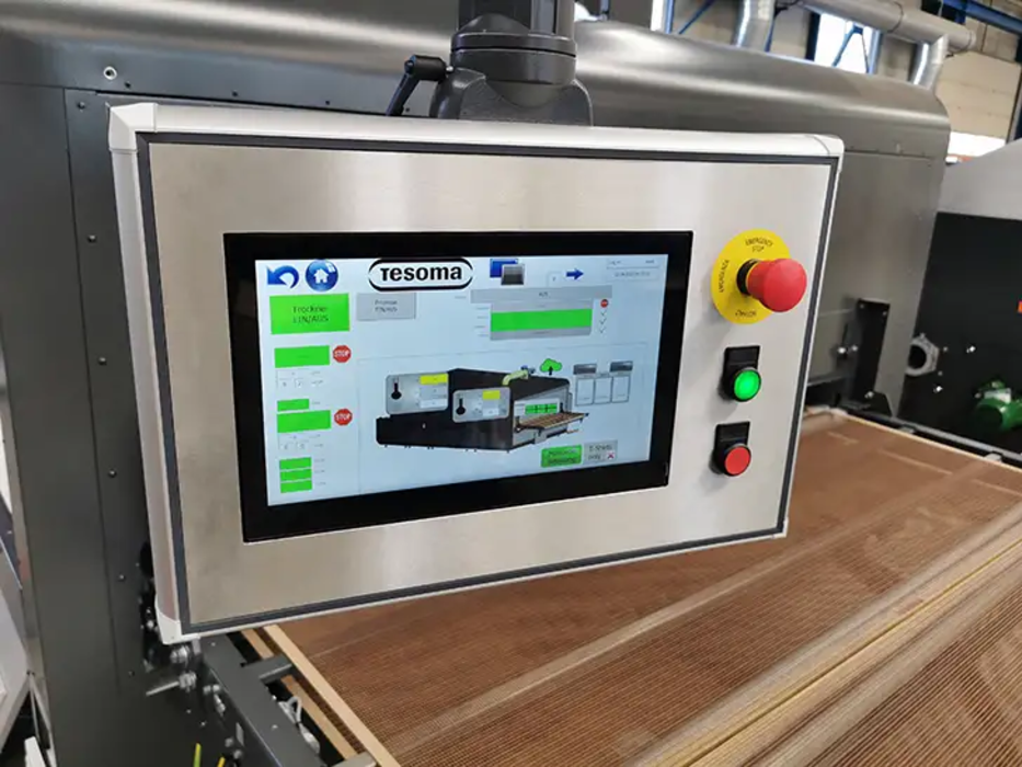
For Tesoma GmbH, two different USB touch panels were to be integrated into an existing Windows Embedded Compact 7 system, which was only available on the target device. The hardware platform was a Beckhoff CX9020 (PLC) with an ARM9 core. The goal was to be able to use new (better/more cost-effective) displays without having to modify the established product through OS or application changes.
Technical challenge:
USB touch is rarely plug-and-play in the field: driver availability, device detection, clean event passing to the input stack, and reproducible behavior—such as after boot or reconnect—must match the existing image and target hardware exactly.
Our Solution
- Analysis of the existing target environment (image/USB ports/input path) directly on the hardware
- Integration of the appropriate touch drivers for both panels into the existing system (including proper device mapping)
- Validation of input in the existing application and stabilization of typical edge cases (start/stop, reconnect, continuous operation)
- Documentation of the integration to ensure the status remains reproducible
Result
The new USB touch panels ran stably and consistently in the target system, allowing the existing application to continue to be used. This made it possible to replace the displays without making unnecessary changes to the overall system—resulting in a robust, maintainable integration solution in series production on Beckhoff hardware.
Read the full case study to learn how SIGMA successfully integrated two USB touch panels.
Start Download
Read the full case study to learn how SIGMA successfully integrated two USB touch panels.
Start DownloadCheck your integration now
To help us assess your issue effectively during our initial consultation, please provide us with some basic technical details regarding the platform, operating system, peripherals, and current status. Especially in embedded driver development, we can evaluate the effort and risks much more quickly if the interfaces, kernel version, and error symptoms are clearly described.
Driver development for embedded systems involves the low-level integration of hardware components such as displays, cameras, touch controllers, audio codecs, wireless modules, and memory and communication interfaces. In practice, this involves not only the driver itself, but also the device tree, initialization, interrupts, DMA, power management, error handling, and seamless integration into the overall system.
Our focus is on kernel-level embedded development and system integration. Depending on the project, we support both Linux-based target systems and legacy platforms when stable integration, porting, or maintenance of existing drivers is required. For us, the key priority is reliable operation on the target device, not just the isolated implementation of a module.
We support I2C, SPI, USB, UART, CAN, RS485, Ethernet, SD/MMC, MIPI DSI, MIPI CSI-2, LVDS, RGB, I2S, PCM, and PDM, among others. Typical components include displays, camera modules, sensors, touch systems, audio components, wireless modules, actuators, and industrial communication interfaces.
Yes. A common use case is porting existing drivers to current LTS kernels, new SoCs, or modified board designs. In doing so, we resolve dependencies, review subsystem changes, adjust configurations and device trees, and stabilize the driver to ensure it is maintainable in production.
Yes. Many projects don’t start with a new development, but with errors that are difficult to reproduce, such as disconnections, frame drops, audio glitches, timeouts, resume issues, or unstable reconnections. In such cases, we analyze data paths, timing, initialization sequences, IRQ behavior, DMA, power states, and recovery mechanisms until a reproducible state is achieved.
Yes. Driver development is only one part of the task in embedded projects. Equally important are board configuration, the device tree, firmware integration, user-space integration, logging, tracing, testability, and documentation. The goal is to achieve a level of integration that is technically transparent and maintainable.
This includes reproducible tests, load and failure scenario analyses, logging and tracing concepts, defined timeout and recovery mechanisms, consistent default parameters, and clear documentation. The goal is not a lab demo setup, but an integration environment that remains manageable in the field over the long term.
It is helpful to provide details about the platform, processor or SoC, operating system in use, kernel version, affected peripherals, current project status, and a brief description of the observed problem. The more specific the information regarding interfaces, error symptoms, and constraints, the faster we can assess the technical scope of the issue.
We will be happy to present solutions for your industry and your processes. Talk to the specialists for SMEs.
request now